& Construction

Integrated BIM tools, including Revit, AutoCAD, and Civil 3D
& Manufacturing

Professional CAD/CAM tools built on Inventor and AutoCAD
A top-down model is a CAD approach that starts with global assembly parameters and subsystems represented by placeholders. In top-down modeling, designers and engineers begin with a model that conveys the design intent for the overall assembly and defines the general relationships between subsystems in a complex product, like an appliance or other machine. Then individual designers or teams working on specific subsystems begin adding in their detail.
Product designers and engineers use several modeling methods: bottom-up modeling, top-down modeling, horizontal or middle-out modeling, and hybrid approaches that mix these methods.
With bottom-up modeling, designers start by working on individual part models, eventually combining them into a separate assembly model. The part models contain the geometry needed for manufacturing. The assembly model has the information on how parts relate to each other and can generate a bill of materials (BOM). With this traditional approach, design changes must be made individually to each interrelated part, which can be a more error-prone method. The bottom-up method is most common with teams working on a design for a product with many standardized relationships between components, such as a bicycle.
The top-down modeling approach can produce great results when designing complex or bespoke systems that need to be changed globally. Consumer electronics, for example, fit subcomponents inside an enclosure usually designed for aesthetic appeal. If the enclosure shape changes, the subcomponents must also change along with it. In such a case, top-down modeling’s global parameter control advances the project with less risk of errors and rework when the design changes.
Perhaps most common is a hybrid approach utilizing standard components like nuts and bolts, library components that a company uses across multiple products, and custom components specific to a product. Designers can control the custom components from the top down without changing the standard or library components.
Perhaps most common is a hybrid approach utilizing standard components like nuts and bolts, library components that a company uses across multiple products, and custom components specific to a product. Designers can control the custom components from the top down without changing the standard or library components.
Several top-down modeling approaches include multi-body modeling, parameter linking, and skeletal modeling, in which a “skeleton” sketch conveys design intent, and designers model the individual components around that overall final assembly—potentially within a single CAD file. The top-down modeling method particularly suits complex products such as automobiles and other vehicles, electronics, appliances, and machines. It also works well for larger teams, where subgroups or individuals work separately on the main assembly, subassembly, or individual components.
CAD software supporting top-down modeling reduces the risk of errors such as mismatching parts that can be the result of the traditional bottom-up approach. Autodesk Fusion uses a single design model that easily allows global parameter changes that update the entire design. Autodesk Inventor supports top-down modeling across its distributed file system using its iLogic rule engine to provide global parametric controls. Both cases make rapid design iterations and changes based on, for example, testing from software simulation much easier than using the disconnected bottom-up approach.
Fusion, Inventor, and other software also accommodate hybrid approaches that combine elements of bottom-up, middle-out, and top-down modeling. In such a case, design and engineering teams may elect to use top-down modeling for their subassemblies, and bottom-up modeling to put together the subassemblies. There’s no single approach that will suit every product. Rather, each project’s needs should dictate the approach that teams take.
While top-down modeling has the overhead of up-front planning and continued coordination between teams, it is the best approach for designing complex or bespoke systems.
With CAD software that supports a top-down modeling approach, changing the main assembly can automatically update the individual components, making it easy to manage iterations and ensure that the associated parts align properly with the overall assembly.
When using a top-down model, all components are designed in relation to each other and to the main assembly within a single file. That makes it easier to edit the entire design and keep it consistent.
If using bottom-up modeling, even small changes to the main assembly or components parts can require corresponding changes to most or all of the design’s components. This can lead to errors, particularly when a team of designers are all working on the same model. Top-down modeling reduces errors and the subsequent rework.
Cloud-based product design software for manufacturing, 3D modeling, electronics, simulation, and data management
Powerful product design and engineering tools for 3D mechanical design, simulation, visualization, and documentation.
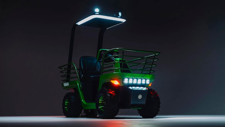
YAMAHA MOTOR
Yamaha Motor and design and technology firm Final Aim co-created a small, rough-terrain EV using Autodesk Platform Services and the generative design capabilities of Autodesk Fusion. The Concept 451 vehicle traverses mountainous, agricultural terrain to assist an aging population with light farm work.
Image courtesy of Final Aim
NASA
NASA took advantage of the crucial benefits possible with Autodesk Fusion’s generative design, such as reducing mass while improving quality, to produce several parts for its Mars Sample Return Mission and EXoplanet Climate Infrared TElescope (EXCITE) missions.
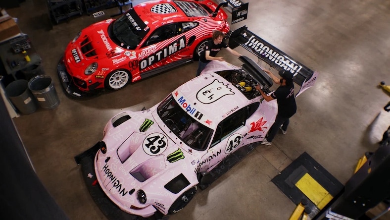
BBI AUTOSPORT
See how the Huntington Beach, California, custom automotive shop, BBI Autosport, “built a car in Fusion,” one bespoke component at a time, with the express purpose of driving the grueling Pikes Peak International Hill Climb.
Learn more about the differences between top-down modeling and bottom-up modeling, as well as how Fusion software enables designers to pursue a hybrid approach that takes advantage of both methods.
In this Fusion lesson, you’ll use the top-down design method to create components and add as-built joints to components.
Create assemblies from components in Autodesk Inventor using bottom-up, middle-out, and top-down modeling methods. Learn all about them here, and you’ll be more comfortable with the common practice of mixing these techniques to match the design intent of a project.
Sharpen your Fusion CAD skills with this two-hour project module, in which you’ll design a customizable assembly using a top-down model.
Learn important basics of CAD design in Fusion software, such as using different methods to create the same geometry and a summary of bottom-up vs. top-down modeling.
The difference between top-down and bottom-up modeling in CAD software for product design is in the approach to how assemblies and components are designed and assembled.
Top-down modeling begins with global parameters, shared datums, and simplified representations of the main subcomponents. Then detail is added to the subcomponents until the design is complete. Top-down modeling is common when the final form requires many bespoke components that will be required to move and change if the final form changes, like in automotive design.
With bottom-up modeling, components are modeled separately and then combined into the final assembly. This is a great option when the relationships between components are standardized and well known.
The advantages of top-down modeling include being better for maintaining the original design intent and ensuring that components fit together precisely. Because parts are designed in relation to each other, this method is good for design consistency and avoiding errors that would require rework.
Changes to the main assembly in top-down modeling can also propagate out to the individual parts when using the right functionality, making it easier to update the design.
Automotive design is often an example of the top down design method. The design begins with a concept for the outer shape and overall function of a car. Its silhouette is determined by factors like drag coefficient and unique styling. That outer form then dictates how certain interior components—such as the seats, dashboard, trunk, and so on—are designed to fit within the car.
Different automotive engineering teams work in parallel on separate components and systems for the car, all in service of the overall concept and design. If other internal systems are not unique to the car, such as the engine and drivetrain, then the design would be more of a hybrid modeling approach.


