& Construction

Integrated BIM tools, including Revit, AutoCAD, and Civil 3D
& Manufacturing

Professional CAD/CAM tools built on Inventor and AutoCAD
Electronic schematic software, also known as electric design automation (EDA) software or electrical CAD (ECAD) software, is used to create and document electrical circuit schematics. Electrical schematic software allows designers and engineers to design the logical representation of their design. It helps them visualize and analyze electrical circuits, ultimately making it easier to develop and communicate complex electrical designs efficiently and accurately.
Electronic schematic design is fundamental to creating consumer products, serving as the technical backbone that ensures functionality, reliability, and manufacturability. This design phase delineates electronic concepts into clear, actionable diagrams, guides the selection of components, facilitates accurate simulations, and streamlines troubleshooting.
At this stage, it is ideal for adhering to industry standards, simplifying the production process, and providing a definitive reference throughout the product's lifecycle. Ultimately influencing the product's market performance and compliance with industry standards.
Electronic schematic designs vary to cater to different functionalities and complexities within consumer electronics. For instance, a block diagram provides an overview of the system, outlining the key components and their interactions, ideal for initial design conceptualization. Circuit diagrams, with detailed representations of the electronic components and their interconnections, are used for the hands-on construction and troubleshooting of circuits.
Electronic schematic design is the critical roadmap that makes sure every electronic product functions as intended. It streamlines development from conceptualization to final production while maintaining industry compliance and operational integrity.
Adopting standardized symbols and components in schematic designs guarantees uniformity and adherence to industry standards. Simplifying the process of understanding and interpreting complex schematics enhances engineering workflows' efficiency and accuracy.
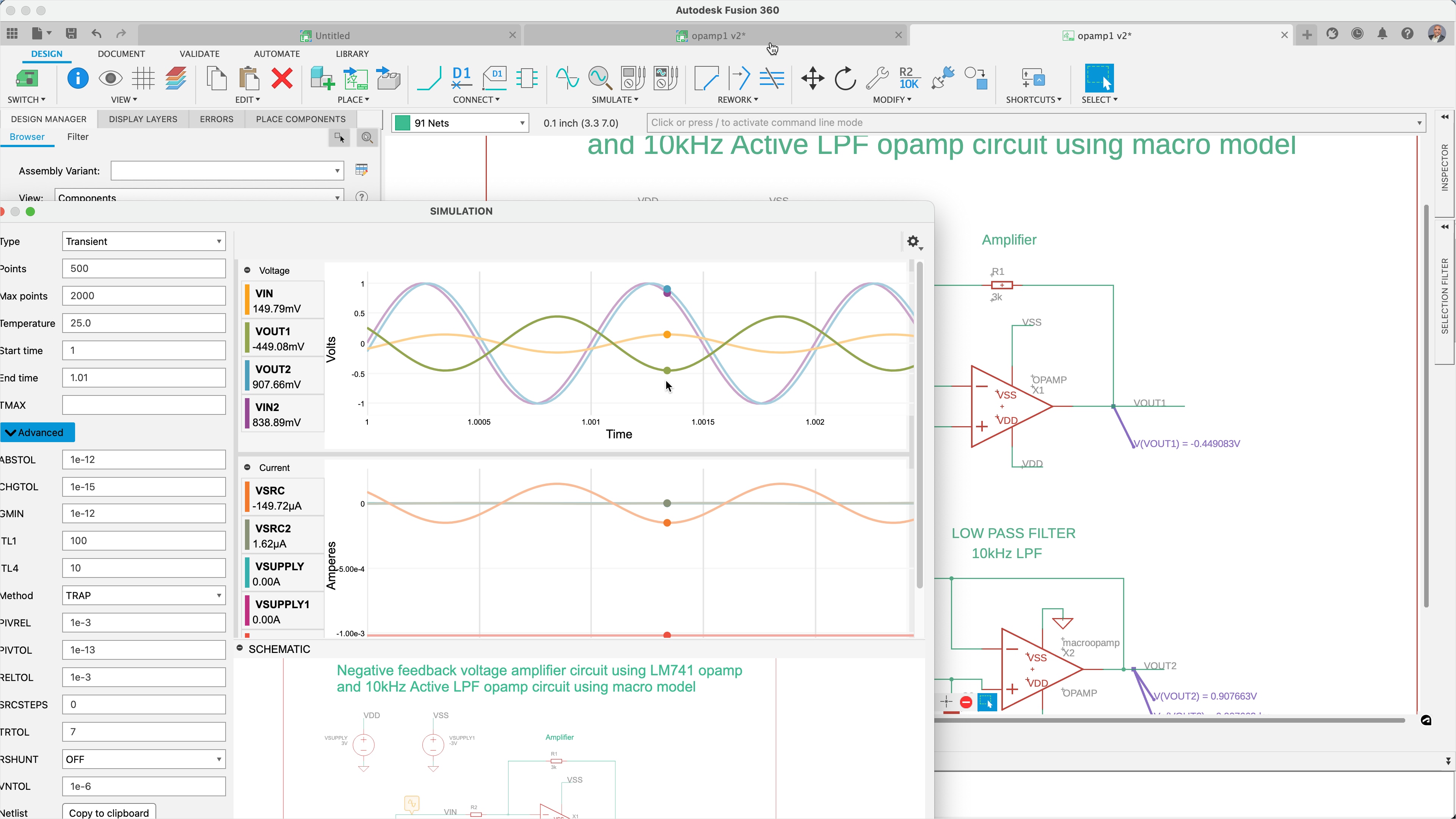
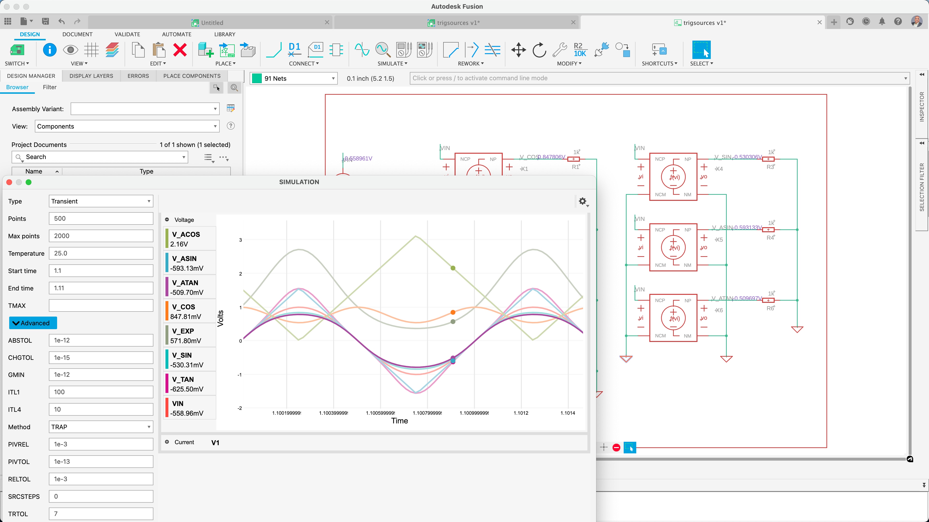
Electrical schematic software like Autodesk Fusion includes simulation tools that allow users to validate and test electrical circuits to identify errors, conflicts, and performance issues early in the design process. This approach significantly reduces the rework potential and optimizes time to market.
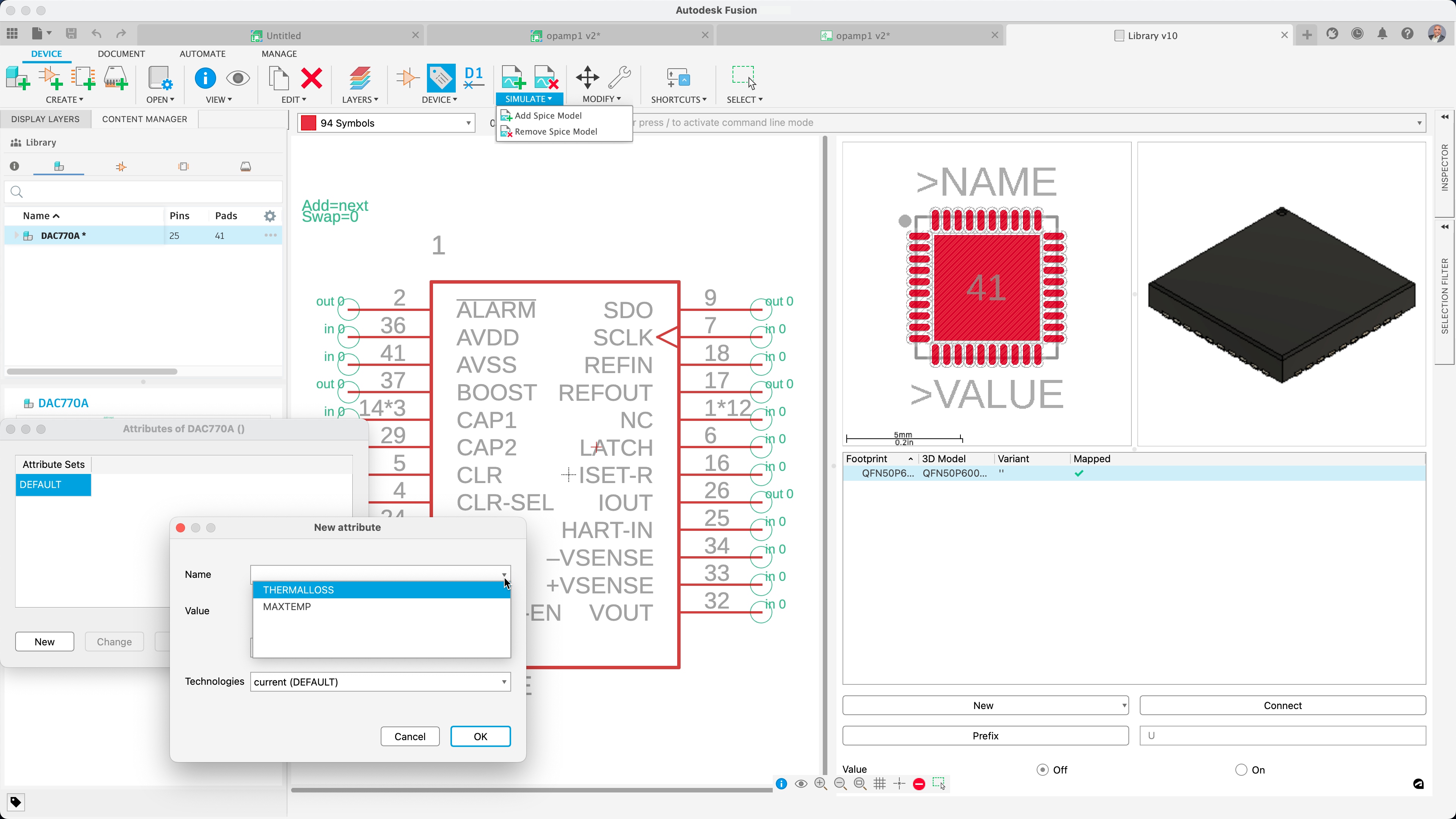
Autodesk Fusion library editor with SPICE model mapping capabilities is crucial. It ensures accurate and efficient simulation of electronic circuits, enabling verification and precision in developing technological solutions.
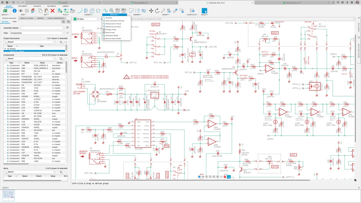
Autodesk Fusion's schematic editing interface and SPICE simulation integration offer a comprehensive solution for electronic circuit design intended to verify expected value results. Resulting in less rework and streamlining time to market.
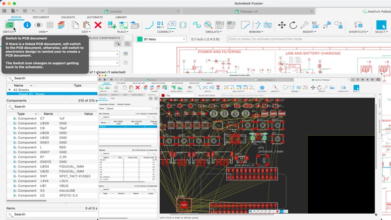
Autodesk Fusion's innovative one-click conversion from schematics to layout, preserving annotations, guarantees designers accurate synchronization, and component selection. Any updates to the schematic are instantaneously applied in the PCB layout.
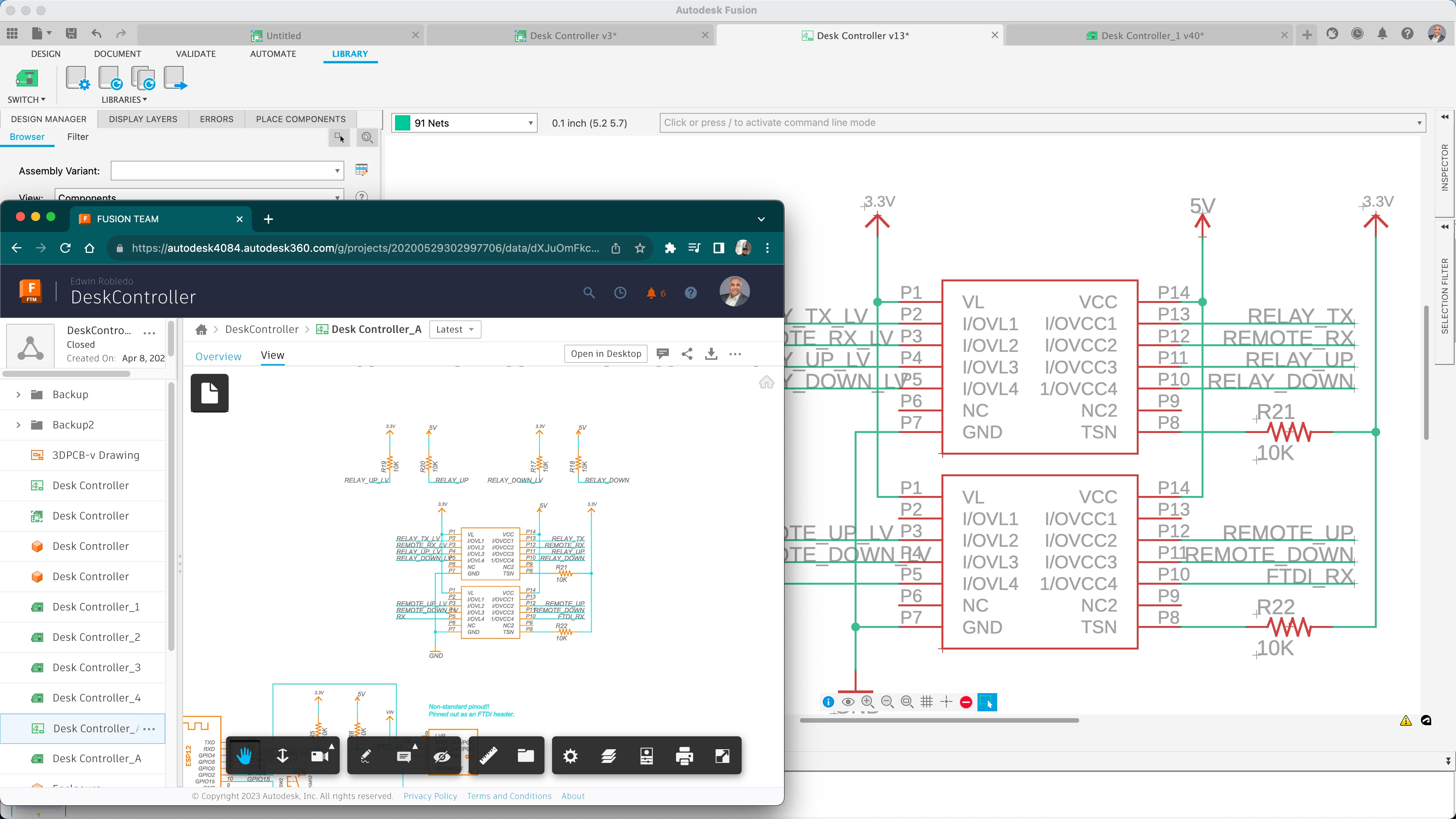
Working on electronic schematics within a collaborative environment is essential for harnessing collective expertise and innovation. It significantly elevating the quality and ingenuity of product design in today's fast-paced industry.
Cloud-based product design software for manufacturing, 3D modeling, electronics, simulation, and data management
Optimize PCB design electromagnetic performance by controlling the impedance of every critical transmission line.
Schematic capture is a process used in electronic design automation (EDA) where engineers and designers create a visual representation of an electronic circuit. This graphical depiction, called a schematic diagram, includes symbols representing various electronic components including resistors, capacitors, transistors, and integrated circuits. Schematic capture is a critical step in the design and development of electronic systems because it allows designers to visualize and plan the functionality of the circuit prior to prototyping and manufacturing.
Schematic capture software, like Autodesk Fusion streamlines the design process, improves accuracy, and facilitates effective communication and collaboration among design team members. It's an essential tool for engineers and designers in the development of electronic circuits and systems.
Schematic capture provides numerous benefits in the design and development of electronic circuits. Here are some key advantages:
Schematic capture offers a clear and organized visual representation of an electronic circuit, making it easy to understand the layout and interconnections of various components.
Detailed schematics allow designers to identify and correct errors early in the design process. This reduces the risk of costly mistakes during manufacturing and ensures that the final product functions as intended.
Schematic capture software often includes tools for automating repetitive tasks like component placement and wiring. This accelerates the design process, boosts productivity, and gives designers the freedom to concentrate on more complex aspects of the circuit.
Schematic capture forms the foundation for subsequent stages of the electronic design process, such as simulation, PCB layout, and testing. It provides important documentation that facilitates collaboration, future modifications, and maintenance, so that all design details are accurately captured and accessible for reference.
Adhering to best practices for schematic capture is crucial for creating clear, accurate, and functional electronic circuit designs. Here are some top best practices:
Always use standard and universally recognized symbols for components to maintain consistency and make it easier for anyone reviewing the schematic to understand it.
Assign unique and descriptive reference designators to each component (e.g., R1, C1, U1) and ensure all labels are clear. This facilitates easy identification and troubleshooting.
Arrange components logically and group related components together to maintain a clean, organized layout to enhance readability and comprehension.
Design the schematic with the signal flow following a consistent direction, typically from left to right and top to bottom. This makes the circuit easier to follow and understand.
Assign meaningful names to nets (connections) to indicate their function or signal type to help identify connections and reduce errors.
Include annotations and notes to provide additional information about the circuit, such as operating conditions, component values, and special instructions.
Indicate power and ground connections using standard symbols to ensure proper understanding of the circuit's power distribution.
Avoid crossing wires when possible and use junction dots to clearly indicate connections and make sure that all connections are unambiguous.
The schematic forms the building block of every electrical circuit, and even if you aren’t designing one yourself, knowing how to read one is invaluable.
Ready for that next great idea for a PCB project? It all starts with your schematic design. Get started with these tips.
Easily pint a schematic in Autodesk Fusion electronics by following these simple steps.
Autodesk is committed to educating tomorrow’s leaders. Get free access to our entire portfolio of products with the Autodesk Education plan.
Yes, electronics schematic software can be used for professional-grade projects. Many professionals in the electronics industry rely on such software for designing and documenting complex electronic circuits. These tools offer a range of features that make the design process more efficient and accurate. Some key features include schematic capture, component libraries, simulation, PCB layout integration, and Design Rule Checking (DRC).
Autodesk Fusion is a great electronics schematics software choice for beginners. With Fusion, you'll gain access to comprehensive electronics and PCB design tools in one product development solution.
No, it is not necessary to have a background in electrical engineering to use electronic schematic software. Autodesk Fusion is user-friendly and has an intuitive interface that makes it accessible to individuals without formal electrical engineering training.
Yes, many electronic schematic software tools come with simulation capabilities that allow you to simulate and analyze the behavior of your circuit designs before physically building them. Simulation is a valuable feature that can help you identify potential issues, validate your design, and optimize performance. Learn how Autodesk Fusion can help.
Electronic schematics and wiring diagrams serve different purposes in the field of electrical and electronic design, even though they may look somewhat similar. An electronic schematic is a representation of an electrical circuit using symbols for components and lines to show the connections between them. It is a detailed diagram that provides information about the components, their values, and the relationships between them in a circuit. Schematics are used for circuit design, analysis, and documentation. A wiring diagram, on the other hand, focuses specifically on the physical layout of wires and connections between components. It shows how the components are physically connected, often with more emphasis on the routing of wires and cables. Wiring diagrams are typically used for installation and troubleshooting.
Electronic schematics are crucial in the field of electronics for many reasons including:
Autodesk Fusion provides a unified product development platform that combines CAD, CAM, CAE tools and PCB, allowing for seamless transitions between schematic capture, PCB design, mechanical design, and manufacturing processes.
Schematic capture provides a clear and organized visual representation of an electronic circuit, making it easier to understand the layout and interconnections of various components. By creating a detailed schematic, electronics engineers can identify and correct errors early in the design process, reducing the risk of costly mistakes during manufacturing. Schematic capture also generates essential documentation that serves as a reference throughout the design lifecycle.
Schematic capture software also includes tools for automating repetitive tasks, such as component placement and wiring, which speeds up the design process. It further serves as the foundation for subsequent stages of the electronic design process, including simulation, PCB layout, and testing, ensuring that all design details are accurately captured and easily accessible. Overall, schematic capture is essential for creating accurate, efficient, and reliable electronic designs, leading to better project outcomes and higher-quality products.

